
Ever wondered how professional 3D artists create intricate, realistic Siemens lenses with geometry nodes in Blender with ease? The secret often lies in mastering Geometry Nodes, but many find it tricky to get started with procedural modeling especially when aiming for precision and efficiency.
In this post, we’ll uncover 7 essential tips that will help you unlock the full potential of Geometry Nodes for creating Siemens lenses in Blender. From understanding node-based workflows to optimizing your modeling process, these tips will guide you step-by-step to ensure you can create stunning, complex lenses with less frustration and more confidence.

Setting Up Your Workspace for Success
When embarking on a complex project like creating Siemens lenses using Geometry Nodes in Blender, one of the most important yet often overlooked steps is setting up a well-organized workspace. A cluttered or unstructured workspace can lead to confusion, wasted time, and frustration. Geometry Nodes can become difficult to manage without the right organization, especially when working with procedural modeling, which relies on a series of interconnected nodes.
The Importance of a Well-Organized Node System
An effective workspace setup in Blender is the foundation of a smooth, efficient modeling process. The key to a successful model is not just knowing how to use the nodes but also organizing them in a way that is intuitive and scalable. This organization helps ensure that you can easily make adjustments, troubleshoot, and expand the design without unnecessary complexity.

Step-by-Step Workspace Setup
Start with a Clean Scene
Before diving into the Geometry Nodes editor, begin by creating a clean scene in Blender. This means deleting any default objects (like the cube, camera, and light) so you have a blank canvas. It’s also a good idea to save a backup of your base scene in case you need to revert to a previous state.
Enable Geometry Nodes in Blender
In Blender’s main interface, switch to the Geometry Nodes workspace. This brings up a specialized workspace with access to the Geometry Nodes editor and 3D viewports, which is ideal for procedural modeling. If you’re new to this workspace, Blender’s default layout should be enough to get started. However, feel free to customize your viewports and panels based on your workflow.
Create a New Geometry Nodes Modifier
To start working with Geometry Nodes, add a new Geometry Nodes modifier to a basic mesh object, such as a sphere or a plane. You can do this by selecting your object in Object Mode, navigating to the modifier tab, and adding a Geometry Nodes modifier.

Node Setup and Grouping
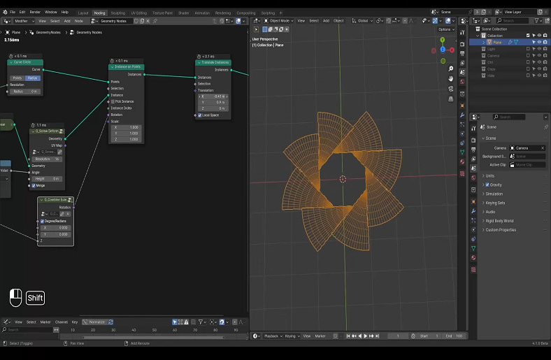
When working with complex models like Siemens lenses, you’ll find yourself using several nodes, such as Subdivide, Curve to Mesh, and Vector Math. Instead of letting these nodes pile up and become hard to read, consider grouping them logically. For example, group all the nodes related to the curvature of the lens in one frame, and group all the nodes related to texturing or surface details in another. Use frame nodes to visually contain these sections for easy navigation.
Label Your Nodes
As you start connecting nodes in your workspace, be sure to label each one clearly. Labeling nodes with short, descriptive names like “Lens Curvature” or “Surface Detail” will make it much easier to locate specific parts of your node network. To label nodes, simply select them, hit N to open the sidebar, and type the desired label in the “Name” section.
Essential Nodes to Include in the Initial Setup
Setting up your workspace also involves choosing the right initial nodes for creating Siemens lenses. Here are some essential nodes to get started:
Input Nodes
- Object Info: Retrieves information about the object geometry, which is essential for modifying the shape.
- Geometry Input: Connects the base mesh to the node network, allowing you to manipulate the model in various ways.
Transformation Nodes
- Scale, Translate, and Rotate: These are basic transformation nodes that you will use to manipulate the geometry of the lens. For example, you can use the Scale node to adjust the lens curvature or Rotate to position the lens at different angles.
- Subdivide Surface Node: Adding extra geometry through the subdivided node can help you increase the resolution of your mesh and allow for finer adjustments later on. This is particularly useful when refining the curvature and smoothness of the Siemens lens surface.
Math Nodes for Precision
- Vector Math and Sine: These nodes will be your go-to for calculating the geometry’s curvature and making sure your lens shape is mathematically accurate. Using Vector Math lets you fine-tune the exact position and flow of the geometry, ensuring that your lens maintains a precise and realistic shape.
Output Nodes
- Geometry Output: Always connect an Output Geometry node at the end of your node network to ensure that your geometry is properly passed back to the 3D viewport. This node is what finalizes your work and renders the geometry you’ve created.

Tips for Efficient Node Management
- Use Layers of Organization: For larger and more intricate models, use frame nodes to separate different aspects of the model, like surface details or structural geometry. This makes the overall node network visually simpler and easier to work with.
- Zoom Out to See the Big Picture: It’s easy to get caught up in the details when working with nodes, but make sure to zoom out periodically to assess the overall structure of your node network. This will help you spot areas that might need optimization or adjustments.
- Use Custom Node Groups: As you create more advanced lens features (like distortion or reflection), you can create your custom node groups to streamline your workflow. Custom groups allow you to bundle several nodes into a single unit, making the network more modular and reusable for future projects.
The foundation of a successful Siemens lens model starts with an organized and efficient workspace. By taking the time to structure your Geometry Nodes setup from the very beginning, you’ll save yourself time and frustration later on in the process. A well-organized workspace not only improves workflow but also ensures that your design remains flexible and manageable. In the next section, we’ll dive into the specifics of creating the base geometry for the Siemens lens, building on this solid foundation for success.
For more insights into optimizing your 3D modeling process, explore our blog post, “The Complete Guide to Best 3D Printer Modeling Software.” This guide highlights essential tools and features that can further enhance your workflow and help you choose the right software for your projects.
Conclusion
By mastering the steps to create Siemens lenses with Geometry Nodes in Blender, you’ve laid the foundation for more complex and precise 3D modeling projects. With a deeper understanding of the techniques and tools involved, you’re now ready to refine your skills and explore new creative possibilities. Keep practicing, experimenting with different designs, and sharing your work to continue growing as a 3D artist.